NEET UG · Physics
Alternating Current
Determine an induced current direction, convert sinusoidal peaks to RMS values and solve a series LCR example without mixing phases.

NEET UG · Physics
Revise the concepts. Try a question. Understand your next step.
22 medium questions available · Try answers free. Sign in to save progress or take a quiz.
NEET UG · Physics
Understand the concept, practise questions and check your learning.
Understand
Read AM envelopes and sidebands, combine power gains/losses and derive geometric horizon reach. Communication systems: connect the signal, spectrum and link
Read the guidePractise
Try 22 medium chapter MCQs. Untimed; check answers and available explanations as you go.
Practise chapter MCQsCheck your learning
Prepare a timed chapter quiz. Choose the available question count and pace before starting.
Prepare a chapter quizThis is chapter practice, not a full-length NEET mock paper.
No revision resources are published for this chapter yet. Use your textbook alongside the guide and practice.
These are playable question counts after quality and duplicate checks.
The practice player uses single-correct-answer MCQs. Chapter quizzes are not full-length NEET mock papers. Check the practice guide and official syllabus sources.
Revise before you practise
No revision resources are published for this chapter yet. Use your textbook alongside the available practice questions.
Read AM envelopes and sidebands, combine power gains/losses and derive geometric horizon reach.
For NEET UG Physics students using this existing chapter catalogue: connect an AM envelope to its sidebands, combine power gains and losses correctly and derive the approximate two-antenna line-of-sight reach.
This guide teaches communication concepts; the archived source and chapter route do not establish current exam inclusion.
A transmitter prepares a message-bearing signal, a channel carries it with loss and possible noise, and a receiver recovers an estimate of the message. Conventional full-carrier amplitude modulation changes a carrier’s amplitude using the message. The carrier frequency, message frequency, occupied sideband span and signal power are different quantities. A geometric horizon is only one constraint on a link; it does not certify adequate power or signal quality at the receiver.
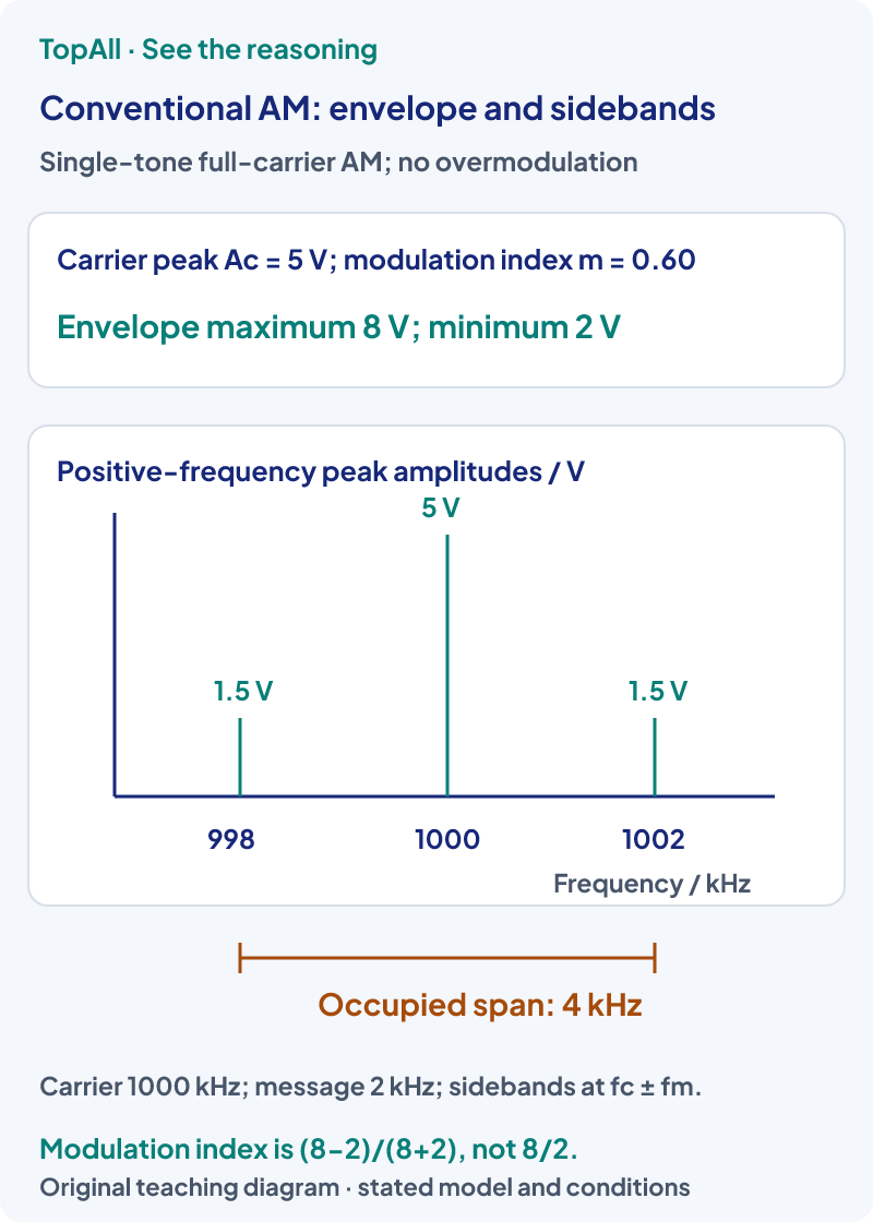
Use the supplied conventional AM model
In conventional AM, keeping the envelope coefficient nonnegative allows a simple envelope detector to follow the message. With m>1, the coefficient crosses zero; the absolute envelope no longer reproduces the intended signed modulation without distortion in that detector. The ideal algebraic three-component single-tone signal does not acquire extra frequencies merely from choosing a larger m; clipping or other nonlinear processing can change that. The familiar 2fm span applies to this double-sideband model, not automatically to FM, single-sideband or every digital system.
A supplied chain starts with 3.00 mW, followed by power gain +10.0 dB, channel loss 16.0 dB and receiver power gain +20.0 dB. Net gain is +14.0 dB because the loss contributes −16.0 dB. Using
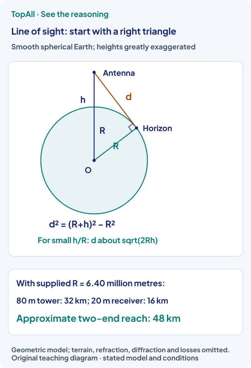
A line-of-sight space-wave model differs from ground-wave propagation along the surface and ionospheric sky-wave paths. Which mechanism is useful depends on frequency, environment, antennas and the link requirements. Increasing a tower height changes a geometric horizon but does not by itself specify every propagation mode or received signal quality. Similarly, a quarter-wavelength antenna estimate is an elementary design scale, not a complete rule for every practical antenna geometry.
For a smooth spherical Earth use supplied , transmitter height ht=80.0 m and receiver height hr=20.0 m. With heights much smaller than R and no refraction, . The contributions are 32.0 km and 16.0 km, so the approximate geometric reach is 48.0 km. Using √(2R(ht+hr)) would give a different, incorrect two-end expression. The exact one-end straight tangent distance is √(2Rh+h²); the neglected h² correction is tiny for these supplied heights. This is geometric reach, not a guarantee of coverage, received power or an unobstructed real path.
An amplifier raises a signal level using an energy supply; demodulation extracts the message from a modulated signal. A receiver may need both, plus filtering and other processing. A larger output voltage does not prove that the original message was recovered faithfully. Describe the stage function before naming it from a familiar block-diagram label.
Do not call the carrier frequency the AM bandwidth or divide envelope maximum by minimum to obtain modulation index. Use consistent Hz, kHz and MHz units. A specified positive loss magnitude contributes negative gain in a signed budget. Distinguish a power ratio from a voltage ratio. Add the two horizon distances in the stated small-height model, and keep its geometric reach separate from a real received-power prediction.
A conventional single-tone AM carrier remains at 1.000 MHz while the message tone rises from 2.00 to 5.00 kHz. What are the new sideband frequencies and ideal occupied span? Does the carrier have to move to 1.005 MHz?
The sidebands move to 995 kHz and 1005 kHz, and their span is 10.0 kHz. The carrier remains at 1000 kHz. A sideband is a distinct frequency component; it does not replace the carrier in this full-carrier AM model.
In the supplied small-height line-of-sight model, raise the transmitter from 80 m to 320 m while the receiver remains at 20 m. What happens to the two contributions and their sum? Does the total reach double?
The transmitter contribution doubles from 32 km to 64 km because distance scales as √h. The receiver contribution stays 16 km. Their sum becomes 80 km, not twice the original 48 km. Only one endpoint changed. All geometric-model omissions still apply.
Derive the AM sidebands from the product rather than recalling a line count. Then write a gain/loss chain and check a two-end horizon calculation. Revisit NEET Electromagnetic Waves for wave quantities, or NEET Semiconductor Devices for nonlinear device and rectifier models.
Chapter practice opens the existing broad Communication Systems pool.
Technical review: Codex (automated). Primary textbook and university teaching sources checked on 23 October 2026. Diagrams, worked examples and questions are original and use explicit models. The archived 2018 Communication Systems exemplar supports concepts; this existing chapter catalogue does not establish current exam inclusion. Human subject review is not claimed.
Before the next set, write the device or signal model and the requested quantity. After a mistake, explain which assumption or comparison failed, then redo the calculation without viewing its answer.