NEET UG · Video

Gamma Rays NEET Notes & MCQs
Learn gamma rays, properties & uses with important NEET MCQs.
5 min video

NEET UG · Physics
Revise the concepts. Try a question. Understand your next step.
10 hard questions available · Try answers free. Sign in to save progress or take a quiz.
NEET UG · Physics
Understand the concept, practise questions and check your learning.
Understand
Check field directions, peak/RMS intensity and the changing electric flux before practice. Electromagnetic waves: connect directions, fields and energy flow
Read the guidePractise
Try 10 hard chapter MCQs. Untimed; check answers and available explanations as you go.
Practise chapter MCQsCheck your learning
Prepare a timed chapter quiz. Choose the available question count and pace before starting.
Prepare a chapter quizThis is chapter practice, not a full-length NEET mock paper.
These are playable question counts after quality and duplicate checks.
The practice player uses single-correct-answer MCQs. Chapter quizzes are not full-length NEET mock papers. Check the practice guide and official syllabus sources.
Revise before you practise
NEET UG · Video
Learn gamma rays, properties & uses with important NEET MCQs.
5 min video
NEET UG · Video
Understand X-rays, production & applications with NEET-level MCQs.
4 min video
NEET UG · Video
Study ultraviolet rays, properties, uses & risks with NEET MCQs.
5 min video
NEET UG · PDF notes
Read PDF · 8 pages →Learn gamma rays, properties & uses with important NEET MCQs.
8 pages
NEET UG · PDF notes
Read PDF · 9 pages →Understand X-rays, production & applications with NEET-level MCQs.
9 pages
NEET UG · PDF notes
Read PDF · 9 pages →Study ultraviolet rays, properties, uses & risks with NEET MCQs.
9 pages
NEET UG · Mind map

Learn gamma rays, properties and uses for NEET UG with TopAll.
NEET UG · Mind map
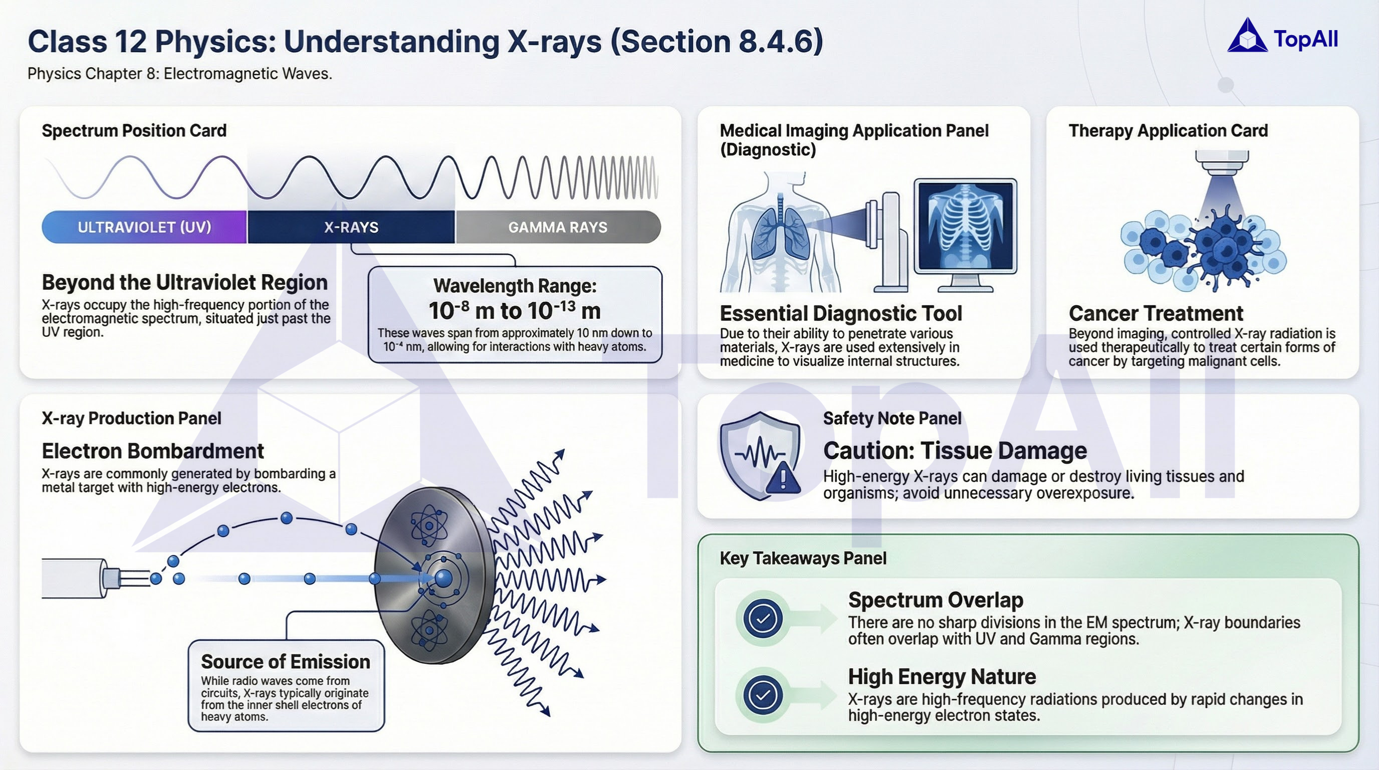
Understand X-rays, production & applications with NEET-level MCQs.
NEET UG · Mind map
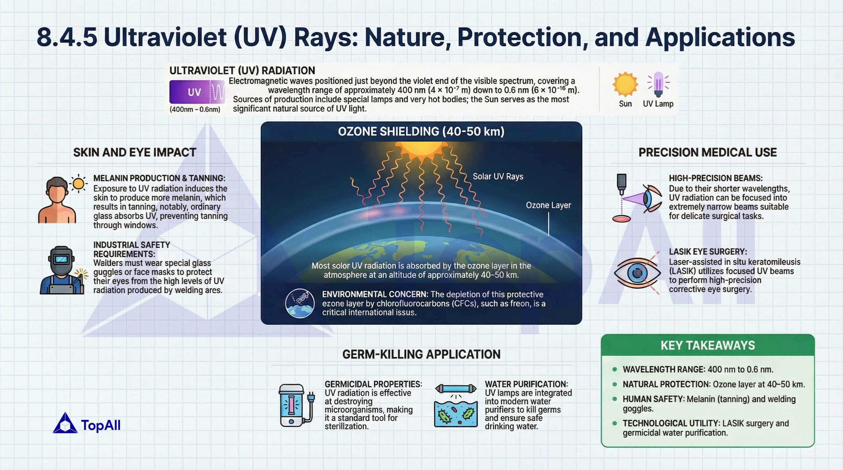
Study ultraviolet rays, properties, uses & risks with NEET MCQs.
Check field directions, peak/RMS intensity and the changing electric flux before practice.
For NEET UG Physics students: find propagation direction from E and B, relate vacuum field amplitudes, distinguish peak from RMS intensity formulas and interpret displacement current in an ideal charging capacitor.
For an ideal travelling plane wave in vacuum, electric and magnetic fields are transverse, mutually perpendicular and in phase. Energy flows in the E cross B direction, and their amplitude ratio E0/B0 equals c. Cycle-average intensity depends on squared field amplitude; photon energy depends on frequency. A charging-capacitor problem asks about a changing electric flux, not an electron crossing every surface. State the medium, waveform and whether a field value is peak or RMS before choosing a relation.
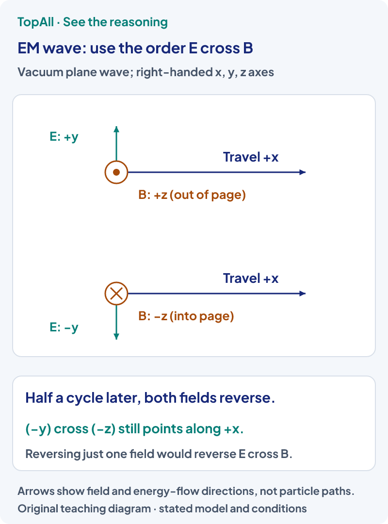
For a linearly polarised vacuum plane wave travelling +x, suppose the electric field at a nonzero positive phase points +y and has peak amplitude E0=120 V/m. The magnetic field points +z, since
In vacuum, . A supplied vacuum wavelength 600 nm corresponds to using c=3.00×10⁸ m/s. At a stationary linear interface into a medium with refractive index 1.50 at that frequency, frequency stays the same, phase speed becomes and wavelength becomes 400 nm. The original 600 nm remains the vacuum wavelength. Do not carry the vacuum speed into the medium while also shortening wavelength at unchanged frequency.
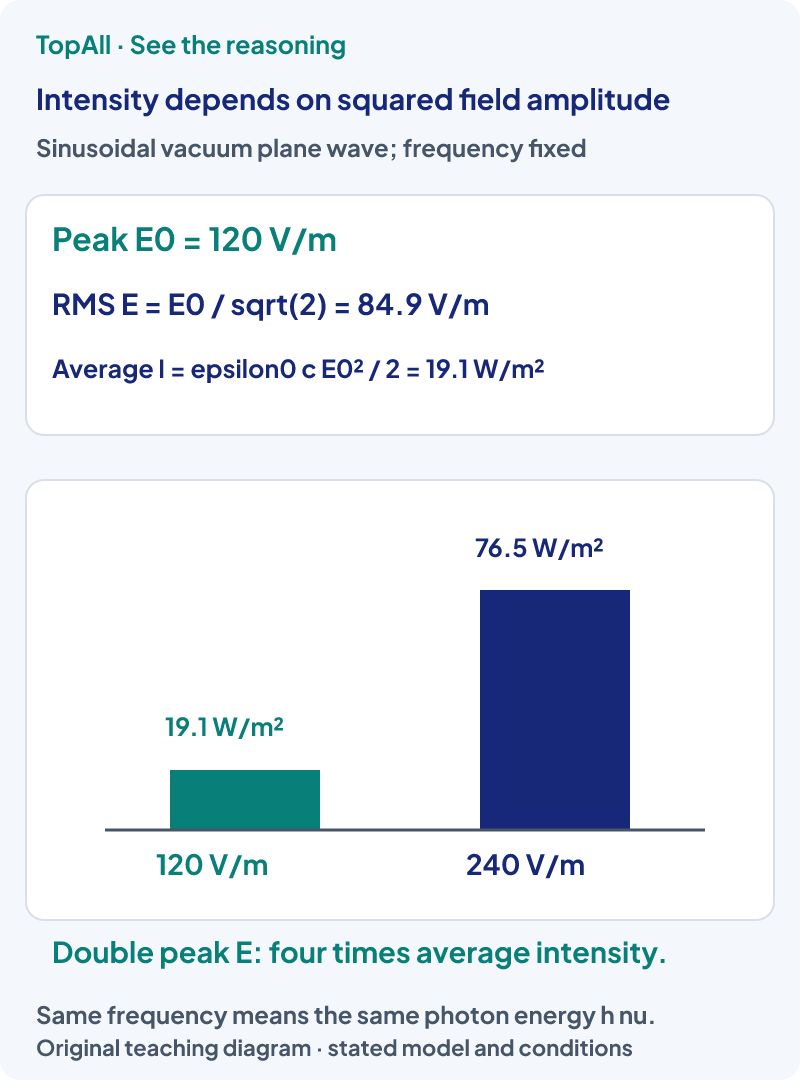
For the sinusoidal vacuum wave use supplied
For an ideal parallel-plate vacuum capacitor, a surface spanning the gap has changing electric flux even though no conduction charge crosses that gap. Maxwell’s displacement-current term is . For a surface covering the plate area in the uniform-field, negligible-fringing model, it equals the charging conduction current in the wire. This is a changing-field contribution to Ampere–Maxwell accounting, not a claim that electrons traverse the ideal vacuum dielectric gap. It vanishes for a static electric flux, even when the flux itself is nonzero.
An ideal vacuum capacitor has fixed C=2.00 nF and supplied voltage ramp . Since Q=CV, the wire charging current is
From long to short vacuum wavelength, the familiar broad order is radio, microwave, infrared, visible, ultraviolet, X-ray and gamma. Higher frequency gives greater photon energy, while all propagate at c in vacuum. The spectral regions have conventional boundaries, and X-ray versus gamma naming also reflects production origin, so a wavelength alone need not settle every label. Different regions do not acquire different vacuum speeds merely because their photon energies differ.
E cross B and B cross E have opposite directions. Reversing both fields together does not reverse the forward wave. E and B do not have equal numerical amplitudes in SI units; their vacuum ratio is c. A peak-field average-intensity formula contains one half, whereas the RMS version does not. Higher intensity at fixed frequency does not mean higher energy per photon. Nonzero electric flux does not imply nonzero displacement current unless the flux changes.
For the illustrated +x wave, E points +y and B points +z at a nonzero phase. What direction would E cross B have if only B reversed? What if both reversed? Does the half-cycle reversal of both fields make the original wave run backward?
Reversing only B gives +y cross −z=−x. Reversing both gives −y cross −z=+x. In the original single travelling wave, both reverse together over a half-cycle and the forward energy-flow direction remains +x. The first case describes a different relative field orientation, not the next half-cycle of that same solution.
For the same sinusoidal vacuum wave, peak electric field is tripled at unchanged frequency. How do magnetic amplitude, cycle-average intensity and photon energy change? Does displacement current stay nonzero in a capacitor merely because its voltage is nonzero?
Magnetic amplitude triples, average intensity becomes nine times as large and photon energy hν stays unchanged. In an ideal fixed capacitor, displacement current depends on dV/dt: a static nonzero voltage gives zero displacement current. Field amplitude, photon energy and rate of flux change are different quantities.
Use a right-handed axis sketch to check E cross B. Then explain the peak/RMS factor before calculating intensity. Continue to NEET Dual Nature to distinguish illumination rate from photon energy, or NEET Atoms for frequency and discrete energy gaps.
Chapter practice opens the broad Electromagnetic Waves pool.
Technical review: Codex (automated). Primary textbook sources checked on 23 October 2026. Diagrams, questions and numerical examples are original and use supplied rounded constants with explicit models. Human subject review is not claimed. These explanations and chapter catalogues do not establish complete coverage of every current exam format or syllabus.
For the next set, name the quantity that changed and the quantity held fixed. After a mistake, explain the wrong shortcut before calculating again.

