NEET UG · Video

Wheatstone Bridge for NEET Physics
Learn Wheatstone Bridge in an easy, exam-focused way with MCQs on TopAll.
6 min video

NEET UG · Physics
Revise the concepts. Try a question. Understand your next step.
15 hard questions available · Try answers free. Sign in to save progress or take a quiz.
NEET UG · Physics
Understand the concept, practise questions and check your learning.
Understand
Check cell emf, terminal voltage, branch currents and circuit power with a consistent model. Current electricity: include the loaded cell before the shortcut
Read the guidePractise
Try 15 hard chapter MCQs. Untimed; check answers and available explanations as you go.
Practise chapter MCQsCheck your learning
Prepare a timed chapter quiz. Choose the available question count and pace before starting.
Prepare a chapter quizThis is chapter practice, not a full-length NEET mock paper.
These are playable question counts after quality and duplicate checks.
The practice player uses single-correct-answer MCQs. Chapter quizzes are not full-length NEET mock papers. Check the practice guide and official syllabus sources.
Revise before you practise
NEET UG · Video
Learn Wheatstone Bridge in an easy, exam-focused way with MCQs on TopAll.
6 min video
NEET UG · Video
Master Kirchhoff’s Rules with clear concepts, formulas and MCQs on TopAll.
9 min video
NEET UG · Video
Understand cells in series and parallel with simple theory and practice on TopAll. .
8 min video
NEET UG · PDF notes
Read PDF · 7 pages →Learn Wheatstone Bridge in an easy, exam-focused way with MCQs on TopAll.
7 pages
NEET UG · PDF notes
Read PDF · 6 pages →Master Kirchhoff’s Rules with clear concepts, formulas and MCQs on TopAll.
6 pages
NEET UG · PDF notes
Read PDF · 6 pages →Understand cells in series and parallel with simple theory and practice on TopAll. .
6 pages
NEET UG · Mind map
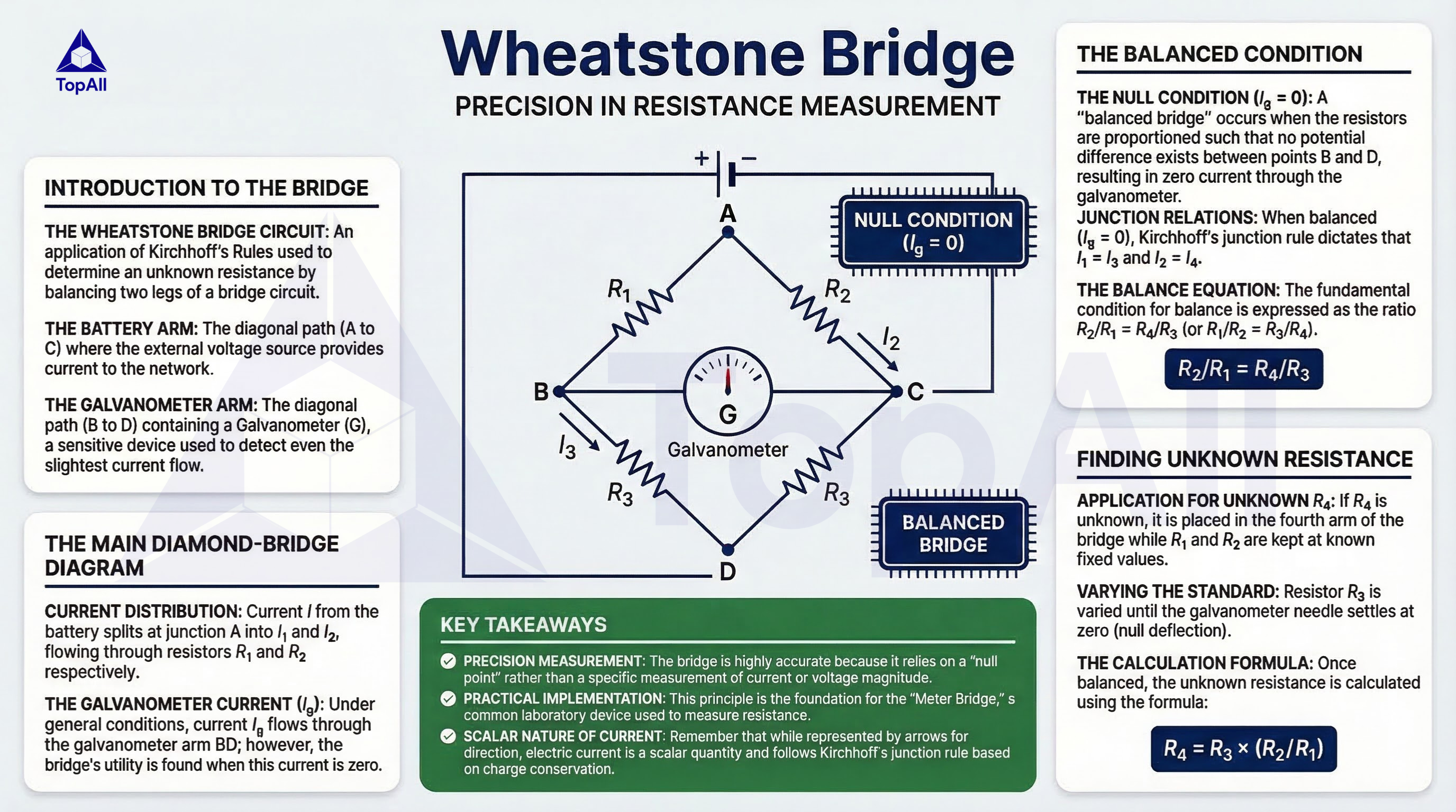
Learn Wheatstone Bridge in an easy, exam-focused way with MCQs on TopAll.
NEET UG · Mind map
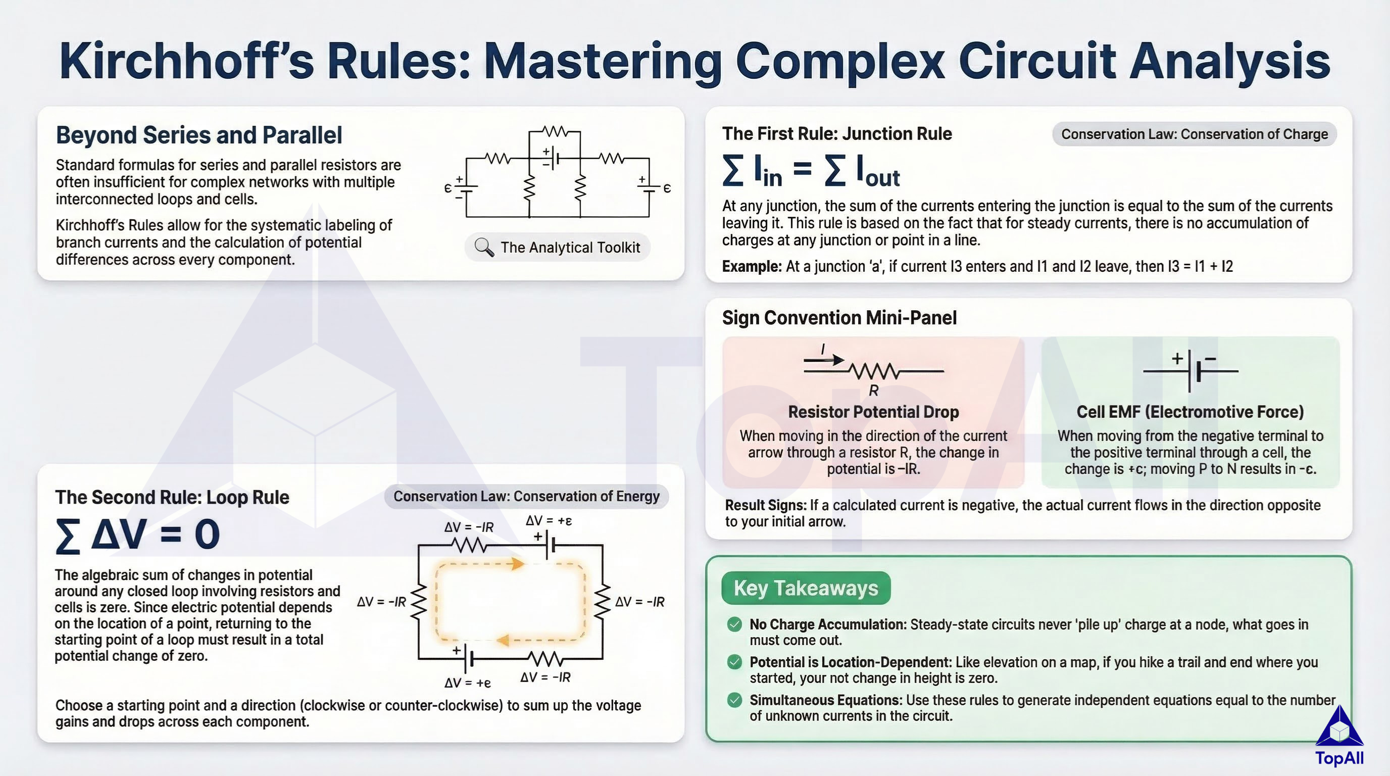
Master Kirchhoff’s Rules with clear concepts, formulas and MCQs on TopAll.
NEET UG · Mind map
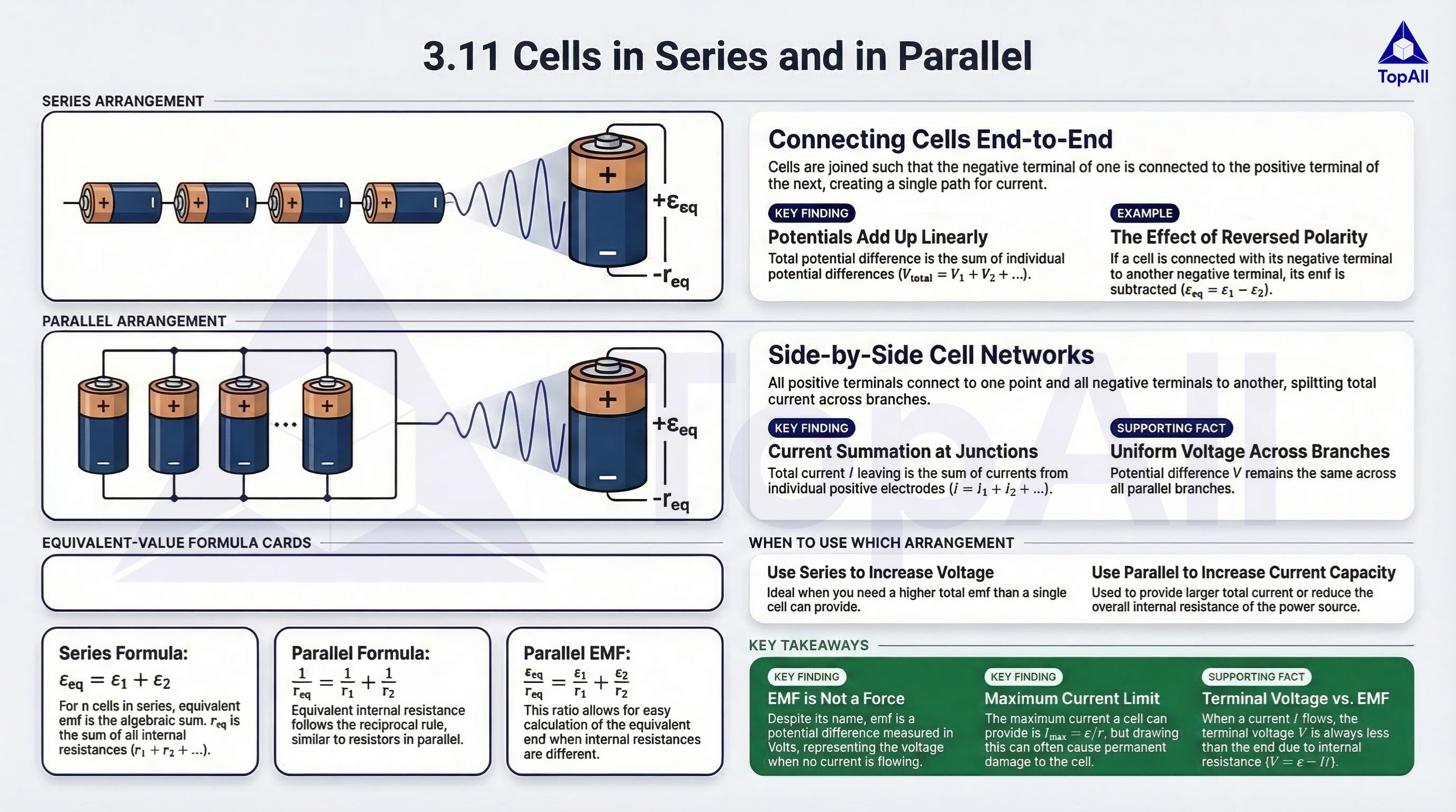
Understand cells in series and parallel with simple theory and practice on TopAll. .
Check cell emf, terminal voltage, branch currents and circuit power with a consistent model.
For NEET UG Physics students: distinguish cell emf from loaded terminal voltage, balance loop energy and branch currents, and interpret drift speed without confusing it with circuit response.
A discharging real-cell model includes an emf in series with internal resistance. The terminal voltage across the external circuit is emf minus the internal current-dependent drop. A changed load can therefore change both total current and terminal voltage. Junction rules account for charge in steady state; loop rules account for energy per charge. Electron drift is an average carrier motion, while electrical response involves the field throughout the circuit.
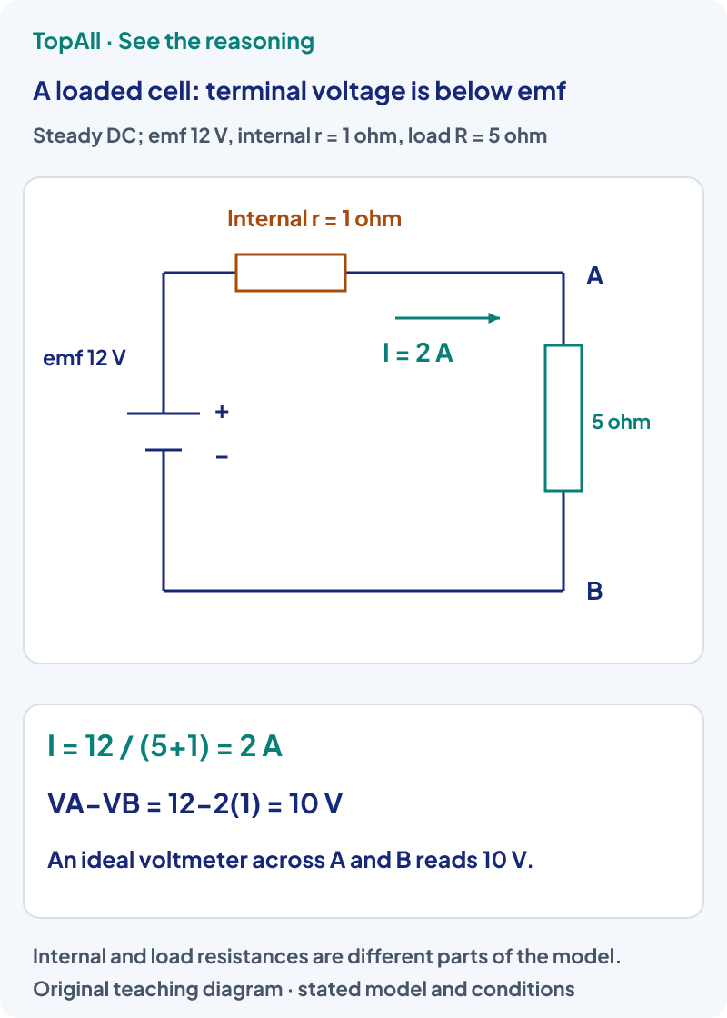
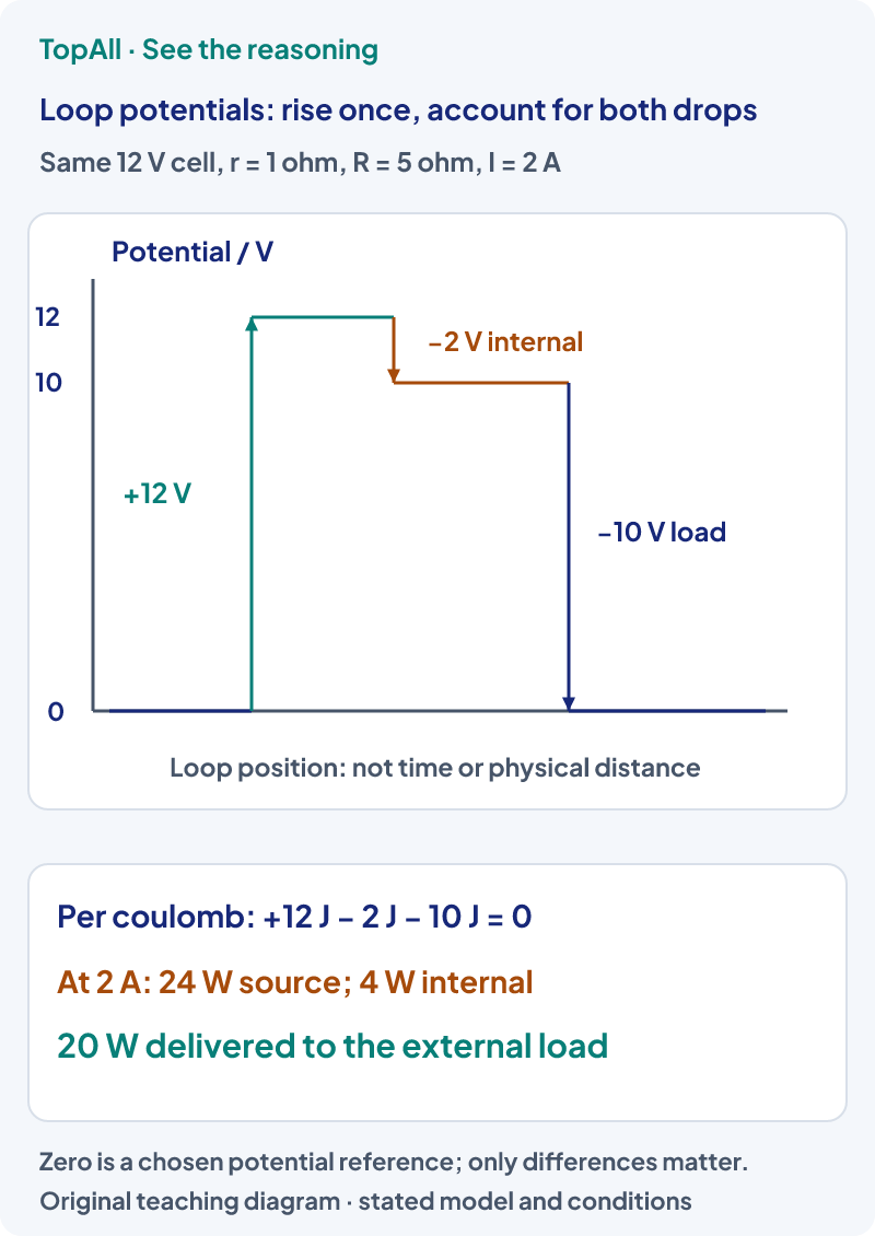
With emf ε=12.0 V, internal r=1.00 Ω and external R=5.00 Ω, total resistance is 6.00 Ω. Thus I=2.00 A and terminal V=ε−Ir=10.0 V, also IR=10.0 V. Load power is I²R=20.0 W, internal dissipation is I²r=4.00 W and ideal-emf power is εI=24.0 W. The power sum closes. If R becomes 11.0 Ω, I falls to 1.00 A while terminal voltage rises to 11.0 V; higher terminal voltage in this comparison does not mean greater current or greater load power.
In the ideal series-emf/internal-r model, an open circuit has I=0 and terminal voltage equal to ε. A load draws current and lowers the discharging terminal voltage by Ir. A nonideal voltmeter itself draws some current, so the word ideal matters when treating its reading as nonloading. Charging uses a different direction of current and the appropriate sign convention; do not carry the discharging subtraction into every battery situation without checking the loop.
Use the same ε=12.0 V and r=1.00 Ω cell. Two external10.0 Ω resistors in parallel have equivalent R=5.00 Ω, so total current is 2.00 A, terminal voltage 10.0 V and each branch current 1.00 A. Add a third identical parallel resistor. Now R=10/3 Ω and . Terminal voltage is , so each branch current is . Three branch currents sum to 36/13 A. The source current increases while each identical branch current decreases, because internal resistance prevents terminal voltage from staying fixed.
Choose branch-current directions before writing the equations. In steady state, total conventional current entering a junction equals that leaving it; this does not require all branch currents to be equal. Across a resistor along its conventional current, potential falls by IR. Across the ideal emf from its negative to positive terminal, potential rises by ε. A negative solved current means that its actual direction is opposite the chosen one, not that the circuit is impossible.
For a supplied metal-wire model use carrier density , cross-section
For a uniform ohmic wire in the stated conditions, R=ρL/A. Stretching a wire can change L and A together; changing temperature can change ρ. The simple fixed-ρ relation should not be extended silently across heating or material changes. Similarly, two parallel branches share the same endpoint voltage, while series components carry the same steady current. Which voltage stays constant depends on whether the source is ideal or has the internal resistance being modelled here.
Include internal resistance before finding current. Distinguish emf, terminal voltage and a resistor’s drop. Check a circuit by both signed potential changes and power. Parallel branches share terminal voltage, but that voltage can change when a real-cell load changes. Do not identify slow electron drift with the full electrical response or set every branch current equal without using the resistances.
For the supplied12 V cell with 1 Ω internal resistance, replace the5 Ω external load by 11 Ω. Find current, terminal voltage and external power. Does the increased terminal voltage contradict a lower current?
Current is 12/(11+1)=1 A, terminal voltage is 12−1(1)=11 V and external power is 1²(11)=11 W. Compared with the original2 A,10 V,20 W case, terminal voltage rises while current and load power fall. The internal voltage drop became smaller; there is no contradiction.
You assumed a branch current of positive direction A to B, but solving consistent circuit equations gives −0.30 A. What does the result mean, and should you discard the solution solely because it is negative?
The actual conventional current is 0.30 A from B to A, opposite the assumed direction. Keep the sign convention consistently in the equations and use the result to interpret the direction. A negative value alone is not evidence that charge conservation or the circuit solution failed.
Explain why terminal voltage differs from emf, then add one parallel branch and predict which currents change. Revisit NEET Electric Potential and Capacitance for energy per charge, or NEET Semiconductor Devices to test a circuit’s device assumptions.
Chapter practice opens the broad NEET Current Electricity pool.
Technical review: Codex (automated). Primary textbook sources checked on 23 October 2026. Diagrams, worked examples and self-checks are original and use stated models and supplied inputs. Human subject review is not claimed. The existing chapter catalogue and these focused guides do not establish complete current exam or syllabus coverage.
Before opening the next set, name the initial state, final state, system and model assumptions. After a mistake, correct the assumption or comparison before repeating the calculation.